E-mail: info@jarorellenor.hu |
|||||||||||||||
 |
|||||||||||||||
 |
 |
 |
 |
 |
 |
||||||||||
| MEMOSTANG EL-04|MB | Program and operation manual - Download latest software | ||||||||||||||
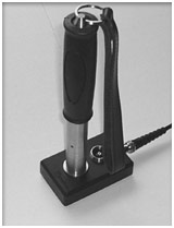
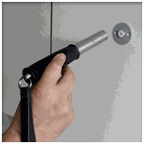
EL-04/MB OPERATIONAL MANUAL The "MemoStang" (Type EL-04/MB) is a handheld intelligent electronic memory device for patrol checkpoint purposes. Practical checkpoint operation is achieved by manually touching the checkpoint's electrical socket with the handy tubular MemoStang module. Connecting action should be easy but distinct, attaching the module tip to the socket contact. While doing so, operator senses a week but definite spring pressure, and should be able to observe the confirming LED light on the side of the module. Once connected, data acquisition and logging attempts will be repeated in 2 seconds intervals. Successful data logging is confirmed by double green LED flash and double BEEP tone. Upon this confirmation signs contact can be released. To avoid unnecessary repeated logging operations, there is a LOGGING DELAY parameter adjustable by the utility program. Minimum time distance of logging events is 100 seconds, the maximum is 36 hours (internal firmware versions earlier than SW27 having no MABISZ approval can set 10 second minimum logging interval). |
 |
|
|||||||||||||
AHIC (Association of The Hungarian Insurance Companies) recommends for safety and security reasons a solid checkpoint fixation separable only by destruction. At the acquisition procedure MemoStang module records into it's internal memory date and time of the logging event, checkpoint type (CheckPoint, ThermoPoint etc.), unique checkpoint identifier, module temperature and supply battery voltage. Log memory can accommodate upto 4096 logged records. It is working with a circular buffer method, overwriting the oldest of these records. Therefore MemoStang contains always the last 4096 event log. When electrical contact quality or timing during the checkpoint operation is inadequate, no logging procedure will take place. Unsuccessful operation - holding the MemoStang longer than 10-15 seconds to the checkpoint - can be recognized by missing LED flash and BEEP confirmation. Cause of unsuccess can be moisture condensation, contaminated or corroded contacts, too short contact time, disconnection of devices during data exchange etc. In such cases please repeat checkpoint operation. If there is still no check confirmation, please report to personnel or supervisory centre the system malfunction. Touching a Personal Identifier (key) with MemoStang module localizes the problem source. If there is a confirmed data transfer, MemoStang is OK, the unsuccessful CheckPoint is probably be out of order. Data acquisition module functionality can be tested without actual logging procedure: shorting MemoStang connector tip with some conductive object (wire, metallic paper clip, knife etc.) there should be GREEN LED flash signals approx. 2 second intervals signalising functionality. Missing LED light shows malfunction, probably bad tip contact or discharged battery etc. These facts are true only, when Logging Delay parameter set in the MemoStang module has expired since the last successful logging action. To assure recorded data reliability and consistency MemoStang intelligent data acquisition module checks all data transferred at checkpoints thoroughly, and if there is even the slightest format error or irregularity, logging procedure won't take place. It means, that logged events certainly belong to actual and successful checking actions, while unlogged (checking action without confirmation) events remain uncertain. This rule assures safe logged data integrity, because fragmented unreliable data could confuse evaluation. It's a good idea to register all Identifier Devices with the PC based utility program before starting to use them. While doing so, we can add free test comments to all Identifiers. Such commentary addition makes future evaluation more comfortable. Such lists can accommodate 10 000 Identifiers with all data and comments for each application. It means that there is no practical limit to the number of Identifiers, the user can organize them in many application groups of maximum 10 000 items each (these lists can be handled as objects or data collections). Lists can be modified only by means of re-listing, i.e. Identifier has to be available at the time of enlisting. This strict procedure strengthens system security. Basic handling and evaluation of the MemoStang data acquisition module is accomplished with a general purpose PC based program utility under (32 bit) Windows versions. Current name of this application program is EL-04/MB while former versions were released under EL_04NT. The new MB suffix shows the AHIC / MABISZ (Association of The Hungarian Insurance Companies) certification, this new approved version is upward compatible with former releases. The utility program facilitates setting of data acquisition module parameters, controls it's operation and checks internal states. Its main purpose is to evaluate and process data records stored in the intelligent data acquisition module, to build up database files in standard CSV format for further post processing with utilities like EXCEL or LOTUS. The application also makes possible simple and direct printing of stored records in order of their calendar dates. In this printing utility result document has numbered pages with "Original" designation as a watermark-like hardcopy effect. If both MemoStang data acquisition module and evaluation utility have new, AHIC approved firm/software (MemoStang SW >= 27 /MB suffix) then hardcopies printed will bear also the /MB sign. |
|||||||||||||||
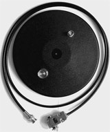
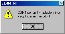
Az EL_04/MB program és az adatgyűjtő együttműködéséhez szükséges egy adatátviteli kábel (DS9097E, DS9097U vagy USB2490 típus) és egy beolvasó adapter (EL-04/MBTA típus) melyek a mellékelt árán láthatók. Az adapter alkalmas mind az adatgyűjtők, mind az azonosító pontok fogadására. A kábel típusa, ha DS9097U akkor a D9 csatlakozón lévő címkéről leolvasható, ha ilyen nincs rajta, akkor DS9097E típus, mely általában, a korábbi rendszerekkel kerül forgalomba. Ha USB2490 akkor az USB csatlakozóról ismerhető fel. To connect the PC running EL-04/MB program and the MemoStang device a data transfer cable (type DS9097E or DS9097U) and a reader adapter are necessary (see figure inserted). The reader adapter is able to connect both Data acquisition modules and Identifier Devices. Cable type DS9097U is marked on its DSUB 9 connector case labelling. Missing label identifies DS9097E cable type usually released with former systems. EL-04/MB utility program is able to handle older EL_03T systems still on the market with their DS9097E adapter cables. It is important to know, that EL-04 data acquisition module operates correctly only with the DS9097U cable set! Present documentation assumes basic PC and Windows user knowledge for those persons installing, running and maintaining the EL_04 data acquisition system. Further administrative personnel trained only for EL_04 usage doesn't need to have deeper, non-EL_04 specific Windows and PC knowledge. PROGRAM DESCRIPTION EL_04/GB utility program standard versions are distributed on CDs, or they can be downloaded from the Internet at URL: http://www.jarorellenor.hu EL_04 program installations starts as usually under Windows running its SETUP. SETUP copies some necessary files to dedicated directories, then English Language EL_04/MB INSTALER screen. During installation the user can change default destination directory from C:\Program Files\EL_04_MB\ and can choose any requested specific path pressing CHANGE DIRETRORY menu item. After selecting directory, installer can start actual installation by clicking on DISPLAY icon. While installing from EL_04 distribution CD, the installation program can display warning messages, when on the computer there are already installed, newer or differing versions or components of the EL_04 program system. It is advisable to keep newer, already existing EL_04 components by pressing Keep soft button if requested by the installation program. In some cases EL_04 installer program recommends restart of the Windows operating system to assure environment, system parameter and variable synchronisation. In such cases please restart the system, and also start EL_04 Install utility itself again to complete the installation procedure. After successful installation EL_04 program icon and window appends to Windows and already existing components, if any was present. From this point on, EL_04 can be started from Windows START -> Programs -> EL_04NT menu. Before running EL_04 the first time, please connect serial data transfer cable to COM1 PC serial port, without connecting the reader adapter to the cable. If the port used isn't COM1 or the cable isn't exactly type DS9097E, EL_04 program starts with the following error message:
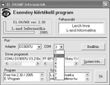
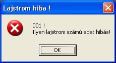
Confirming this message by pressing OK, start window of EL_04 appears: Pressing SETTING soft key actual settings are stored, control returns to the MAIN menu window, see following figure. Error message described above (INVALID CABLE or COM PORT) will appear again only if stored settings are conflicting with actual serial data transfer conditions, or the cable itself is defect. INFO menu panel contains some additional information about the program itself and it's drivers (versions, access path), about the user and the system and lists author references. During contacts are shorted, grey coloured OPEN message changes to red SHORTED in STATE field, indicating the action. Removing the short STATE field switches back to grey. This procedure indicates fully functional data transfer between PC and reader adapter. From this point on, EL_04 program and the configuration can be used to enlist Identifiers and process data acquisition modules. Old cable type DS9097E and certain PC configurations produce eventual malfunctions in serial communication, causing STATE field to change SHORTED with no obvious reason. Immediate remedy is to restart the system, for long term cable replacement to DS9097U is recommended. Enlisting There are two main logical Identifier types. In the first group are CheckPoint category Identifiers having code function only. These devices can be indoor, outdoor units, Personal Identifiers, their code number ends always with 01 string. To the other group belong Technology Identifiers, these are able beyond code function to measure some physical parameters like temperature or pressure (ThermoPoint, AnalPoint). Code of devices has an ending like 28, 20. Before their installation it's recommended to assign some text information to the Identifiers. It makes easy to identify them, using practically understandable mnemonic names instead of long and difficult numbers. This assignation procedure is called Enlisting. Assignation info is stored in LAJSTROM.DAT file in the program system actual work directory. As a default this file is an empty file, during Enlisting new assignations will be appended to the file. It's important to make regularly backups of this file, and keep is at a safe place because additional enlisting action or refreshment of existing list items is possible only if Identifiers are available, i.e. to rebuild the Identifier database either valid backup LAJSTOM.DAT or re-read of the Identifier is needed. It is not recommended to make any changes or patches manually or with editors on the LAJSTROM.DAT. Use Enlist function to make this file consistent if damaged, or reload backup LAJSTROM.DAT. Enlist utility checks file and specifically identifier code integrity and gives error messages if inconsistencies are found.
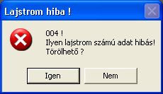
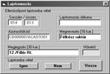
At the first case in the above example Identifier Code is all right, only additional information is damaged. Pressing OK "Damaged Data" comment is written into ANNOTATION field, and enlist integrity is recovered In the second case Identifier Code itself is also damaged, only item delete operation can recondition the database. If there are several damaged identifiers, one by one recover operation is nor efficient enough. Exiting EL_04 utility, reload backup LAJSTROM.DAT into the work directory is the remedy. This method is also recommended if system re-installation is needed. If EL_04 finds no errors in LAJSTROM.DAT, normal program operation can be started. Important notice: Do not use LAJSTROM.DAT filename for other purposes on the computer running EL_04! Unintended write operations to this file may corrupt data integrity and make further system operation impossible. Enlist database can contain maximum 10,000 identifier records. If it is insufficient, program can be installed in more than one work directory, resulting as many enlist database files (each consisting of max. 10,000 identifiers) as many work directories are used. One Identifier record can appear in more databases, helping to build up databases for various purposes in differently named work directories, practically under project names. Please observe, that EL_04 utility itself can run only as a single application! Enlisting operation is started from the program's ENLIST menu. Selecting ENLIST function, insert the Identifier to be enlisted into he reader adapter socket. Hold the device in place till the identifier's code number appears in the IDENTIFIER field of the menu window. Once the IDENTIFIER field is filled with the code read, device can be removed. Now we can add commentary information to the enlisted Identifier: the primary ANNOTATION field can take up a 16-character string, for Personal Identifiers practically the bearer's name, for other devices location description etc. Additional 30-character string can be entered into COMMENT field as further information to the Identifier. There are no restrictions using characters in this field, e.g. checkpoint sequence, name extension; post-processing data for further programs in any combination are only few possibilities. Important is, that these fields will be added to the Identifier's code number, enlisting date and serial number in all processed outputs as reports, abstracts, printouts, screens etc. When an Identifier is left unlisted, it has only the unique, built-in identifier code number. It is important to enter at least one valid character into ANNOTATION field, primary ANNOTATION and additional COMMENT fields should describe together and uniquely the Identifier. Actual enlisting will occur pressing YES soft key in the menu. LAJSTROM.DAT file will be updated, enlistment date, time and serial number will be added. Enlistment calendar and real time information is the data got from PC clock/calendar function. If the reader adapter reads an already enlisted Identifier, previous enlistment data appears on the screen. If we do any changes and validate these by pressing YES, enlistment date/time will be updated. If we'd like to discard changes avoiding updating, please press NO. Reading ThermoPoint type identifier to test it's internal thermometer chip, the utility displays the temperature measured continuously if THERMO field is selected. To switch to the main screen of the program press RETURN. To view the LAJSTROM.DAT file content (devises listed with additional information) select the LIST menu function. We can navigate in this adjustable window with the help of scroll bars. In the LIST menu, DATABASE FILE NAME field describes the complete access path of the LAJSROM file, withal showing the actual work directory. To delete an Identifier record from the enlistment database, double-click on the ENLIST NUMBER field of this item.
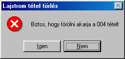
Confirming the record removal operation, identifier code will be replaced by DELETED script, and all commentary text information of the record will be deleted. One such operation frees one position in the database file, but this free space fills only at the next new enlistment operation, rendering the freed enlist number to the newly enlisted Identifier. It means that more than one identifier can be ordered to the same enlist number - when meanwhile delete operations took place. We can make a listing about existing enlisted identifiers to the hardcopy output using REPORTS \ ENLISTMENT PRINTOUT menu point. To print the program needs at least one Windows printer peripheral installed. During printout dialogue panel appears, where the user can select and confirm the requested printer type. For actual printout page layout see the following example: All pages of the printout document are numbered and bear watermark-similar "ORIGINAL" inscription. For text-format archiving and post-processing purposes of the enlistment database select FILE \ ENLISTMENT SAVE CSV menu item. After entering filename and confirming the action, list file containing ASCII strings separated by commas - known as CSV file format - will be generated. This format is readable for programs like EXCEL or WORD. With the help of special utilities (not a part of the EL_04 program system) the original LAJSTROM database file can be regenerated. This operation can be a last remedy if the original database file is corrupted and has no backup. CSV file structure and content example: - EL-04 - Enlistment CSV file name: .\lajstrom.csv Enlistment No Identifier code Assignment Comment Enlistment date
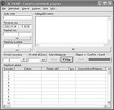
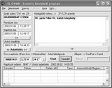
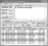
Data acquisition module operation To process the data acquisition module with the program, insert the module as figured. Either enlisting function, or handling of the acquisition module is available within the program simultaneous operation is not possible. After inserting the module to the reader adapter socket, on the screen appear general module data, computer's internal clock and date in the SYSTEM CLOCK field. It is advisable to set the PC internal clock/date accurately with Windows utility to assure correct operation time base reference. Accurate and continuous real time clock data can be obtained form various sources, e.g. DFC mouse, central time base references accessible via Internet, network service utilities etc. Especially important is correct date and time setting to synchronize operation of several data acquisition modules in time getting exactly and accurately timed system. Data acquisition module actual internal time is displayed in the MODULE TIME field. To synchronize the module to the computer's internal clock press the >> symbol key under the field. From this point on, data acquisition module internal clock runs synchronic with the PC clock, LAST TIME SET field is filled with the synch moment clock and date. This information is stored in the module itself, too. For practical purposes it's advisable to make personal notes about the event for future use. One of the most important factors for system security and safety is time synch, logged by the data acquisition module. Another as important aspect is, that data acquisition module can record events only in their strict order of appearance defined in absolute time. For example, if a logical event sequence isn't accompanied by monotonously increasing time marks, there should be clock resets during acquisition event series - date of such intended or accidental resets is fixed in the LAST TIME SET field. Conclusion: long time logging system reliability and credibility can be tested and traced with the help of time stamps added to event records, monotonously increasing time marks. All program controlled time settings/resets are recorded. All data mentioned above appears in all output formats (report files, printouts, screens etc). SERIAL NUMBER field contains unique Identifier factory number. SERIAL NUMBER comment is followed by "SW Ver: X.Y " information showing actual data acquisition module internal firmware version (as of 2001-DEC Version 2.3). RECORDER NOTICES field can take up 123 character long text string added to the data acquisition module. Pressing soft key below this field >> writes this additional information into module. If the characters in the field seem to be rather grey than black, please press REPEAT soft button tore-read module information, until all characters in NOTICES field change to black. Boxed comment e.g. >> 23/123 shows that23 character places are used of the total 123 available. RECORDS TOTAL field contains aggregated number of records stored in the data acquisition module. It is a non-resettable total of totals for the whole module lifecycle. TEMPERATURE and BATTERY fields show respective physical parameters effective at the time of the last recording. Pressing the soft key > below these fields initiates temperature and battery voltage measurement, writes actual values into the fields. This can be considered as a physical operation check. Soon as measurement is finished, the module gives a short beep and green LED flash to indicate readiness. Actual operating parameters are written in their fields, which can be tested continuously. This information is also measured and recorded at Checkpoint Operations. Data acquisition module is battery operated, containing a special long life, wide operating temperature range and high capacity Lithium battery as energy source with nominal 3.6 V voltage. If its voltage drops below 3.1 V at 20C°, replacement is needed. If the battery voltage is lower than 3.48V, BATTERY field background colour changes to red, indicating a nearing battery lifecycle end. Lower half of the screen is filled with tabular event logbook. At the logbook's upper border number of event since last delete operation, and last delete date and time are displayed. To delete logbook entries press soft key DELETE LOGBOOK. Entering YES and confirming by pressing OK starts delete operation. Logbook event counter will be resetted; last delete operation date/time is recorded as described above. It's important to know, that this procedure doesn't actually delete information stored in the data acquisition module, but rather makes them inaccessible for normal read operations. Data acquisition module stores always the last 4096 event records. We can access with an optional utility all these information (not a part of EL_04 system). Data read procedure is initiated by pressing START soft key. DATA READ comment appears in the STATE field, a green bar diagram helps to trace the read operation proceeding. Depending on computer speed and amount of data to be transferred, read procedure can take a few seconds up to several minutes. During processing (data structure check) thorough record format checks make sure that no corrupted data will be transferred / loaded into the program tables. There are maximum 4096 data record lines in the table, each containing following information: serial number, date and time of recording, identifier type, identifier's code, description (annotation), parameter (battery voltage, temperature), comment, enlistment date, enlistment serial number. A checksum calculated in the preparation phase will be added to this information, during later data transfers and processing data sets are checked on integrity using that checksum, therefore high degree of data reliability is maintained and assured. At the end pf the processing data sets are sorted by date/time and are stored in a table with numbered rows. Row and column scroll operation help to overview this table containing all recorded data information. Data records are entered into the logbook in strictly increasing date/timestamp order. Last record written contains the latest data set in time. When a data record proved to be erroneous (inconsistent), then the according data table row will be filled with " - - " characters. When an error occurs only during processing the identifier code, an error message ERROR IN LINE will be written into the logbook. Therefore if an event is recorded in the logbook with its identifier code, it is a surely existing, true event. Reliability and accuracy of date/time stamp depends on accuracy of the internal real time clock set in the data acquisition module, i.e. basically the system operator is responsible for time checks and settings. Event logbook column contents are as follows:
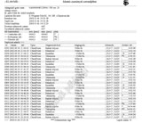
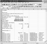
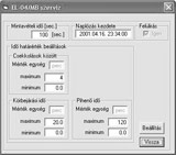
Logbook contents can be displayed and examined on the screen using scrollbar tools. We can print hardcopy reports choosing REPORTS \ LOGBOOK PRINTOUT menu item. To print hardcopies, the user must have at least one printer installed under Windows operating system. Starting LOGBOOK PRINTOUT interactive print window appears, here the printer can be selected and the printout confirmed. In additional windows we can choose printout range - entering starting and last row to print by serial numbers as follows: Pressing OK selected logbook range hardcopy will be printed as follows: All document of result document have numbered pages with a watermark-like hardcopy effect "Original" designation. This printing layout assures hardcopy based system reliability and confidence. It is recommended to store logbook hardcopies as evidence of events in those cases where certain event occurrence must be proved later, because document originality and authenticity is assured by this system. When we wish to archive or process logbook contents in text format, we can select FILE \ LOGBOOK SAVE in CSV FORMAT menu item. In appearing interactive window we can enter file name, and confirm the file save action. The selected logbook portions will be written in ASCII form into this file, fields will be separated by comma characters (CSV format). CSV format can be easily prostprocessed by programs like EXCEL or WORD. Nevertheless, this format isn't as much authenticated as true "Original" hardcopies, because originality isn't assured and cannot be proved. See also the following example. EL_04 program has a SERVICE menu item, where we can set some of the data acquisition module's operating parameters. Attention! False data acquisition module parameter settings can cause virtual disfunctionality of the unit! LOGGING DELAY parameter sets the minimum time interval between two logging events in seconds. During this LOGGING DELAY time, thus between logging events or checkpoint operations there is "no sign of life" from the data acquisition module, its power consumption is minimal. When the EL_04 system is used to check guard personnel activity, we can set the minimum time elapsed between two adjacent checkpoint operations. Therefore the sentinel person must stay at least for LOGGING DELAY time in the field to achieve consecutive CONFIRM signals from the unit. In other cases, when e.g. ThermoPoint type devices are connected (electrically) continuously to the data acquisition module, then repeated automatic recording will occur as set by the LOGGING DELAY time parameter. In this case we can use the system as a mobile temperature measurement and recording device. This LOGGING DELAY in minimally 100 seconds, and can b set between 100 and 1000 seconds by double-clicking on this screen field. Pressing OK the new time value will be written in grey into the field. To achieve permanent setting, final confirmation of all parameters by pressing soft key FINALIZE is needed. All parameters set will be written to the data acquisition module, and then after a short time all parameters are re-read and displayed again, as functionality check. LOG START parameter is a date/time mark, from this date on is logging activity enabled. If LOG START date/time is not yet reached, checkpoint operations result in one green LED flashlight and one short beep, but there will be no recording. To change LOG STAT parameter, double-click on the field and proceed as follows: Pressing OK, the new time value will be written in grey into the field. To achieve permanent setting, final confirmation of all parameters by pressing soft key FINALIZE is needed. Window box OVERWRITE cannot be changed, logging method is in all cases OVERWRITE style, i.e. records will be circularly overwritten after 4096 log events. AnalPoint measuring adapter settings are valid only, when AnalPoint device is installed and is connected permanently to the data acquisition module. BACK soft key returns to the program main menu window. Pressing REPEAT soft key, the reader adapter re-reads data acquisition module attached, parameters can be examined, checked or re-set as needed. If there is no module in the reader adapter when REPEAT is pressed, the system returns to its default values. REPEAT soft key changes to EXIT, here we can leave EL_04 program. Otherwise program can be ended by pressing X, or ALT F4 in the main menu . Menu item TERMINAL serves future purposes, when EL_04 system will be accessed remotely (under development). To get further information and/or access code (password) to program updates please visit us writing or calling to: Appendix: Dictionary: Hungarian - English
|
|||||||||||||||
| Járőrellenőr - All Rights Reserved 2007 | L-and Informatika | ||||||||||||||

